June 3, 2014

A Modern Farmhouse: Construction Update

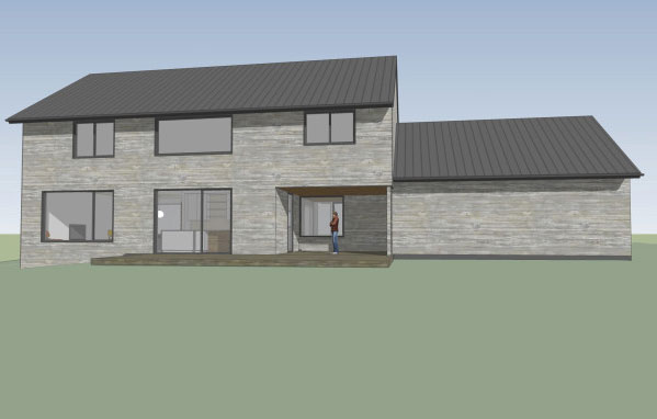
A lot of construction happened since the last blog post and we have moved into our (mostly) finished house. It is proving to be a very comfortable home and we can hardly wait for winter to see how it performs in the cold. Okay, maybe we can wait a bit for that.

Entry
Earlier we explored the foundation system and in this post we’ll discuss the wall and roof systems. Let’s quickly review the four basic control layers to be considered in every building enclosure:

1. Water:  Keeps bulk-water out of the structure.

2. Air:  Keeps conditioned air inside and unconditioned air outside.  Air also holds moisture, so air moving through the structure is a bad thing.  As the saying goes, build tight and ventilate right.

3. Vapor:  Controls the amount of vapor permeance through the structure.  It’s inevitable that some amount of moisture will get into your walls, so you need to allow them to dry-out.

4. Thermal:  AKA insulation… Slows the transfer of heat through the structure.

The wall we constructed is a ventilated rainscreen system.  A rainscreen is an exterior wall construction where the siding stands off from the weather barrier creating a capillary break allowing for drainage and evaporation.  Some of the benefits of this system include prolonged life of the siding and finish (due to temperature and moisture equalization of the material), minimizing the chance of water intrusion into the wall structure, and keeping the weather barrier dry, thereby prolonging its life.  To minimize the penetrations through the weather barrier the wall construction was sequenced in this manner:  layout studs on floor deck, fasten plywood sheathing to face of wall, place rigid foam board over plywood (only tack in place), roll out building wrap over rigid foam board (do not fasten), place 1x3 furring strips over building wrap (located over each stud), fasten furring strips tight using 4” screws.  The furring strips are what hold the building wrap and the insulation board in place. Below is a list of how the 4 control layers were handled:

Water:  The metal roofing and underlayment keeps bulk water out of the roof system.  The cedar siding is a rainscreen, keeping the bulk water out of the structure.  Behind the siding the 3/4" air gap and building wrap act as the drainage plane for any water that makes its way through.

Air:  Although great care was taken to control air intrusion at the exterior of the structure by using flashing tapes and minimizing penetrations, the primary air control layer is the gypsum board on the walls and the underside of the roof truss (see red line on diagram).  The gypsum board was sealed to the wood structure to prevent air movement from the conditioned spaces into the wall and attic cavities.  We used an EPDM gasket that was easy to install and provides an excellent life-long seal.  We also used a similar gasket at the wall sill plates to seal the inconsistencies in the wood construction between wall and floor.  All rim joists at floor to wall junctures were sealed with spray foam as this is a notorious air-leaking point.

C:UsersptaylorDropboxTaylor Residencex_plans Model (1)

Wall Section Diagram

Gasket_sm

EPDM Gasket

Vapor:  The vapor retarder employed is latex paint over 5/8” gypsum at exterior walls and the 2nd floor ceiling.  It’s inevitable that some moisture will make its way into the wall system, so allowing the structure to dry back to the inside is important.  Latex paint creates a vapor retarder, not a vapor barrier which would not allow the structure to dry.  The attic is continuously ventilated at the eaves as well as the ridge which keeps moisture from building up within the roof structure.

Thermal:  The structure of the wall is 2x6 wood studs at 24” o.c. and the cavities are filled with high density fiberglass batts (R-21).  To enhance the thermal performance the exterior walls have 2” of XPS (R-10) continuous rigid insulation board. This continuity of insulation eliminates the effects of thermal bridging at the studs, resulting in a very high performing wall system.  The attic is filled with blown-in fiberglass at an R-value of 100. The trusses were designed with a raised heal to allow for more insulation at the typical eave pinch-point.  Care was taken to seal the baffles to the structure so air from the eave vents would not move through the insulation, stripping it of its thermal performance. The continuous eave and ridge vents keep the attic from becoming super-heated in the summer and keep it cool in the winter which prevents icicles from forming.

Entry-day

Combined with the foundation systems previously discussed and the Intus Eforte ultra-high performing triple-glazed windows, the building shell of the Modern Farmhouse should prove to drastically minimize the amount of energy needed for heating and cooling, all while keeping our family very comfortable.

April 7, 2014

A Modern Farmhouse: An Introduction

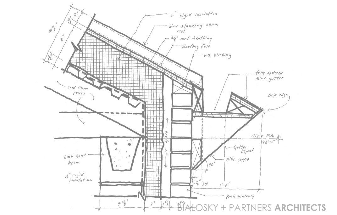
The sheer variety of building systems that can be used to enclose a structure is astounding.  We’ve all come across architects or builders who believe they know the absolute best way to construct a particular building type in a particular environment, but I don’t believe such absolutes truly exist.  The appropriate design solution should be arrived at using a balance of project goals, location, efficiency, economy, skill of trades persons, budget, aesthetics, etc. Over the next few months we'll examine the building enclosure of a low-budget, low-energy-use house that my wife and I designed and are currently building for our family.

Panorama of site during excavation.

IMG_2105

The very first CMUs are laid on the site for the Modern Farmhouse.

The design intent of this project was to create a simple, right-sized modern farmhouse.  One that is beautifully integrated into its site, filled with natural daylight, healthy, comfortable, and uses half the energy of a comparable code-built house….all while sticking to a tight budget.  To achieve these goals we had to find a cost effective high performing enclosure system, supplemented by paying careful attention to site orientation and maintaining a compact 2-story form.  Decisions were not just based on researching system performance (thank you, www.buildingscience.com ), but also became about choosing systems that our subcontractors would be familiar with.  Because we are general contracting the project ourselves and cannot be on site with the subcontractors at all times, a lot of thought was put into choosing the right foundation, wall and roof systems that subs could work with, had construction tolerance, and would still perform. Let’s start with a brief overview of the four basic control layers to be considered in every building enclosure:

1. Water:  Keep bulk-water out of the structure.

2. Air:  Keep conditioned air inside and unconditioned air outside.  Air also holds moisture, so air moving through the structure is a bad thing.  As the saying goes, build tight and ventilate right.

3. Vapor:  Control the amount of vapor permeance through the structure.  It’s inevitable that some amount of moisture will get into your walls, so you need to allow them to dry-out.

4. Thermal:  AKA insulation… Slow the transfer of heat through the structure.

Slab-On-Grade Detail

A building needs to be constructed from the foundation up, so that’s where we’ll start. We chose a fairly typical basement structure for Northeast Ohio:  12” CMU on concrete spread footings.  What’s different is the type, location and amount of insulation used.  To reduce thermal bridging from the earth through the concrete slab and CMU wall, a continuous layer of rigid insulation board was used and the insulation value of the whole system was then increased by adding a 2x4 wall with high density fiberglass insulation. The wall performs on par thermally with insulated concrete forms (a high-performing wall system Bialosky +Partners has used in the past), but is less costly to construct.

Foundation Section of Taylor Residence

Below is a list of how the 4 control layers were handled:

1. Water:  The CMU walls were damp proofed and a drainage board placed over top.  Together with gravel backfill and foundation drainage that daylights on site the basement should be dry for a lifetime (did I really just say that?).

2. Air:  The air control layer is at the interior side of the CMU.  Extruded polystyrene (XPS) insulation board was attached with mastic and all joints were sealed to create this layer.  High Density closed cell spray foam was installed to seal the first floor system to the XPS.  The floor to wall juncture is a notorious air-leaker, so spray foam is a perfect product to seal this area up tight.

3. Vapor:  Polyethylene plastic was placed between XPS and concrete slab, and sealed to the CMU wall. This keeps vapor occurring in the ground from driving through the floor slab into the house. Vapor permeable latex paint over 5/8” gypsum board was used as the vapor retarder at the walls.  It’s inevitable that some moisture will make its way into the wall system, so allowing the wall to dry back to the inside is important.  That’s why we used a vapor retarder, not a vapor barrier which would not allow the wall to dry.

4. Thermal:  The XPS board used as an air barrier pulls double duty.  2” XPS (R-10) was used on the walls, and 2” XPS was placed under the entire concrete slab.  This continuity of insulation also reduces thermal bridging at the foundation wall and slab.  A wall of 2x4 wood studs at 24” o.c. with high density fiberglass batts (R-15) is used to supplement the XPS insulation.  5/8” gypsum board not only finishes the wall system, but is required to meet flame and smoke spread requirements per the building code (XPS foam is not allowed to remain uncovered within an occupiable area). Overall this foundation system is well insulated, didn’t require any special training for the subs, was easy to build, and was inexpensive.  I think it was the appropriate choice for this particular project. Next time we’ll examine the house’s wall, floor and roof systems.

February 13, 2014

BPA University – Digital Fabrication + Scripting in Architecture

Last Friday I put together a small informal internal lunch and learn for the BPA staff in which we looked at and discussed digital fabrication equipment and construction techniques.  Based off of the course that I taught at Kent State University last semester, the discussion of various techniques and uses in architectural applications became very exciting.  We also began to discuss and share how the process of scripting and parametric design could impact our design.  I shared various precedent from firms such as SHoP Architects, design work by Alex Hogrefe, and even included some of my own work on a new bookshelf that is in process.  Feel free to walk through the Prezi Presentation below!

[prezi id="<http://prezi.com/jhgvwfbugqxo/macraild-dig-fab-and-parametric-modelling-lunch-and-learn/#>" width=500 height=400 lock_to_path=0]

January 16, 2014

BPA Goes to Greenbuild 2013

Philadelphia Greenbuild 
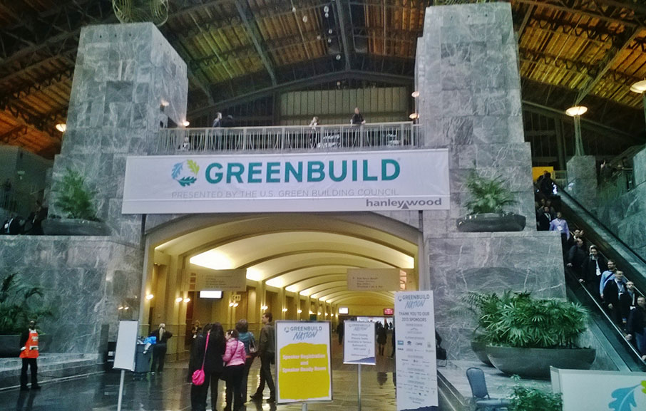
Once a year, for about a week, all eyes in green building culture turn towards a single focus - it’s been San Francisco, it’s been Toronto, Chicago, Phoenix, and Boston.  Every year it is a new city for Greenbuild, the world’s largest conference and exposition dedicated to the green building industry.  This year, its 20th year running, it was Philadelphia.  I had the pleasure of representing Bialosky + Partners Architects at Greenbuild 2013 this past November.  The international convention and expo hosted approximately 30,000 attendees from 90 different countries and touted speakers as varied and prestigious as Rich Ferizzi, President & CEO of the USGBC; Michael Nutter, Mayor of Philadelphia; Nate Silver, author of The Signal and the Noise; and the keynote address was given by former Secretary of State and former First Lady, Hillary Rodham Clinton. Greenbuild 2013 Philadelphia Convention Entry Greenbuild is more than just a world-class convention.  It is also a networking smorgasbord and showcase of all things sustainable.  This year the expo hall was packed with over 800 exhibitors of sustainable products and services.  Huge multinational corporations displayed their full suite of green products right next to small startup companies rolling-out their newest gadget or software to a captive, and captivated, audience. Greenbuild 2013 Convention Multiple parallel tracks of educational sessions provided a plethora of learning opportunities.  Lectures ranged from changes in the newest version of ASHRAE 90.1 to low energy lighting strategies, and from net-zero design to insights on the commissioning of existing buildings.  Some of the most highly anticipated and well attended sessions dealt with LEED v4, which was officially introduced at Greenbuild 2013.  It’s a lot to wrap your head around. Throughout the entire convention, a simple but powerful idea kept presenting itself to me… this is not an isolated, short-lived movement.  This is not a passing fashion.  This is not a fad. Greenbuild 2013 Philadelphia Convention Floor Whether the adjectives used to describe it are “earth-friendly”, or “sustainable”, or “eco”, or “green”… the fact is, the world is changing.  Greenbuild is one time a year when those people keeping track congregate and try to direct that change to be something manageable, and positive, and fun.  Another successful year… now on to 2014… this time it’s New Orleans.

December 17, 2013

401 Lofts

Young professional Akronites are filling the newly opened upscale apartments of 401 Lofts, in Downtown Akron, OH. Named for its address, 401 S. Main Street, the contemporary loft apartment building boasts walkable urban living in the same fashion of “22 Exchange”, its neighboring sister-building that houses Akron University Students. The two buildings, both designed by Bialosky + Partners for client Richland Properties, have started to visibly spark a new vibrancy of Akron’s downtown, and has in turn, become a highly desired location to live, work and play.

Exterior View of 401 Lofts in downtown Akron, Ohio. Designed by Bialosky + Partners Architects. Photography By Scott Pease Photography.

Comprised of predominantly Studio and 2 Bedroom lofts with a handful of 3 and 4 bedroom units, 401 Lofts has spacious floor to ceiling windows, hardwood floors, and 9’ or higher ceilings to achieve the “loft” feel.

View of a typical studio unit of 401 Lofts in downtown Akron, Ohio. Designed by Bialosky + Partners Architects. Photography By Scott Pease Photography.

The ground floor of 401 Lofts activates the site with 4300SF of amenities in its clubhouse, including a game/billiards room, lounge, coffee bar, fitness center, 24-hour tanning bed, and additionally outdoor swimming pool and deck.

Ground floor common space in 401 Lofts in downtown Akron, Ohio. Designed by Bialosky + Partners Architects. Photography By Scott Pease Photography.

Now for the design challenge: to achieve the client’s suite / bed count for 401 Lofts, the building required an additional story of apartments above the 4 story building base (totaling 5 stories). To stay on budget, wood frame construction fit the bill, but the framing system can only be employed on buildings totaling 4 stories or less. The solution? A hybrid system of ICFs (Insulated Concrete Forms) that provides for a noncombustible exterior wall construction and the needed fire rating , while still allowing wood frame construction for the building interior. Imagine ICFs as giant, EPS foam Legos which add a tremendous R value (R-22) to improve the building’s thermal performance. This naturally cuts the client’s anticipated utility bill significantly.

Construction photo of 401 Lofts in downtown Akron, Ohio, featuring the ICF walls system. Designed by Bialosky + Partners Architects.

This hybrid wall construction, coupled with energy-efficient, thermally broken aluminum windows and energy-efficient PTAC heating and cooling units (which have the ability to be monitored by building management) collectively work in harmony to deliver an energy-conscious design.

Exterior View of 401 Lofts in downtown Akron, Ohio. Designed by Bialosky + Partners Architects. Photography By Scott Pease Photography.

The sheer length of the building is quite breathtaking – at 330’, the façade could very easily become monolithic. By taking advantage of the tapering site (north to south), the building steps at strategic intervals driven by the standard ICF sizes, reducing the need for field modifications and custom fabrication.  401 Lofts is clad in a Tuscan brick, fiber cement lap siding and champagne-colored metallic panels that fluctuate in their color based on viewing angle. By exhibiting the street names in raised steel panel lettering at the building corners, we rooted the building to its place and (geo)graphically related the building its adjacent sibling, 22 Exchange.

Exterior View of 401 Lofts in downtown Akron, Ohio. Designed by Bialosky + Partners Architects. Photography By Scott Pease Photography.

ARCHITECT:  Bialosky + Partners, LLC INTERIOR DESIGNER:  Kathy Andrews Interiors (Houston, Texas) STRUCTURAL, CIVIL AND LANDSCAPE ENGINEERING: Thorson Baker Associates MEP ENGINEER: TES Engineering SURVEYING: L.V. Surveying, Inc. CONSTRUCTION COST: approx. $12 million

Bialosky Announces Transition Plan

X